Ghana-Kumasi
Traffic Light using Arduino – A Beginner Project
If you are a beginner this project is for you. In this you will find how to make Arduino Traffic
Components & Supplies for the Project
| Item | Quantity | Purpose |
|---|---|---|
| Arduino Uno (or compatible board) | 1 | The main microcontroller that runs the program |
| Breadboard | 1 | For easy, solderless connections |
| Red LED | 1 | Represents STOP light |
| Yellow (Amber) LED | 1 | Represents READY/CAUTION light |
| Green LED | 1 | Represents GO light |
| 220Ω Resistors | 3 | Protect LEDs from too much current |
| Jumper Wires (Male-to-Male) | 6–8 | For connecting components to the Arduino |
| USB Cable for Arduino | 1 | To upload the code and power the board |
| (Optional) Buzzer | 1 | For adding sound (pedestrian crossing alert) |
| (Optional) Push Button | 1 | To simulate pedestrian control |
Apps / Software You’ll Need
| App / Software | Purpose | Link |
|---|---|---|
| Arduino IDE (Windows/Mac/Linux) | Write and upload your Arduino code. Official and free. | https://www.arduino.cc/en/software |
| Arduino Cloud (Web Editor) | Online version of the IDE. No install needed. Good for Chromebooks or shared PCs. | https://create.arduino.cc/editor |
| Tinkercad Circuits (by Autodesk) | Free online simulator to build and test Arduino circuits virtually before wiring the real components. | https://www.tinkercad.com/circuits |
Platforms / Hardware
| Platform | Why Use It |
|---|---|
| Arduino Uno | Easiest board for beginners; widely supported. |
| Arduino Nano | Smaller version; good if you want a compact traffic light project. |
| Arduino Starter Kit | Includes Uno board, LEDs, resistors, breadboard, and jumper wires — perfect if you don’t have any parts yet. |
Connect With Me
Below is a video that walks you through every step of assembling and running the traffic light using Arduino.
Click Here – Full Step-by-Step Guide
YouTube – Watch the Video
Hackster – Project Page
Arduino – Official Arduino Resources
Introduction
In this project, you will learn how to make a simple traffic light using Arduino. It involves a little bit of code and a very simple circuit that is perfect for beginners.
The video further down this page walks you through all the steps to complete this project. Using just an Arduino board and a few LEDs, you will replicate the sequence of a real traffic light. The Arduino code acts as an internal timer and keeps the cycle running until you disconnect the power supply.
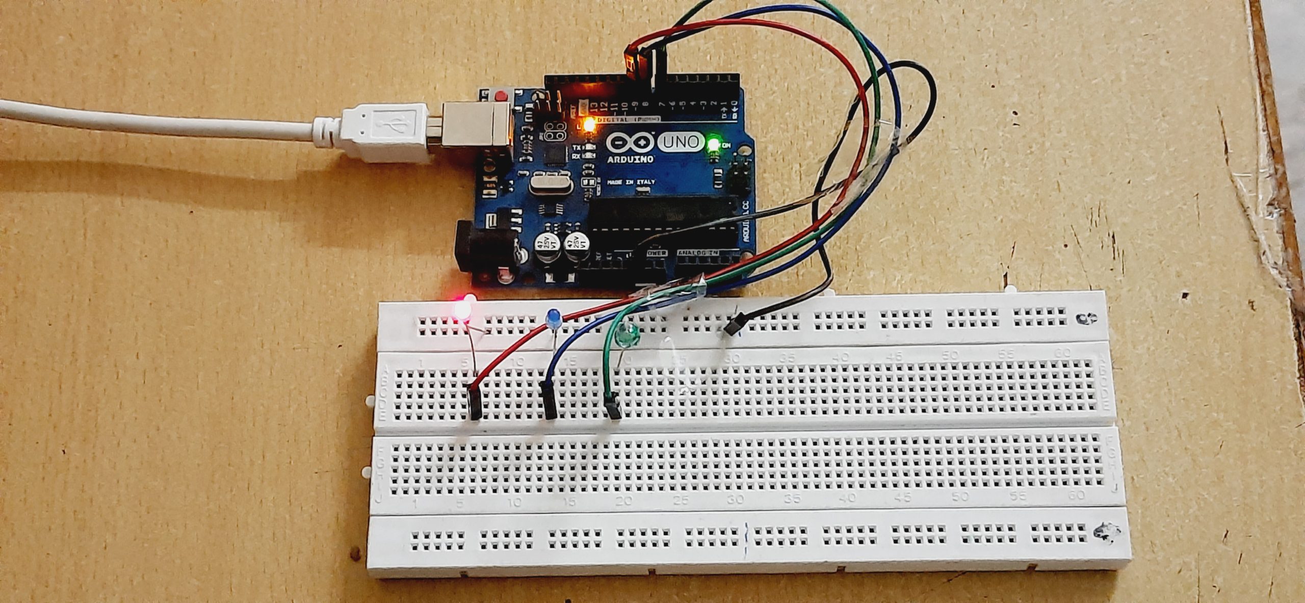
Working Basics
The LEDs are powered by an Arduino UNO board. Once you upload the code to the board and power it on, the LEDs start blinking like a real traffic light:
Red Light: 15 seconds
Yellow Light: 6 seconds (in this version, a blue LED is used for yellow)
Green Light: 20 seconds
You can adjust these timings inside the code to match your needs.
Usage
This project has multiple uses:
A simple introductory Arduino exercise for beginners
A miniature traffic light demonstration for classrooms or exhibitions
A base to expand with more LEDs, sensors or buttons for advanced features such as pedestrian crossings or countdown timers
Next Steps
After mastering the basics, you can:
Add a buzzer to simulate pedestrian alerts
Use a button or sensor to create a smart traffic light
Display a countdown timer with an LCD screen

Hookup
- Hook the GND pin (Negative Pin) of all led to Pin GND of Arduino.
- Connect Red LED VCC Pin (Positive Pin) to Pin 9 of Arduino.
- Connect Yellow LED VCC Pin (Positive Pin) to Pin 8 of Arduino.
- Connect Green LED VCC Pin (Positive Pin) to Pin 7 of Arduino.
Uploading and Testing
- Copy or download the code attached with the project.
- Watch the video to Check the testing Click here
int red = 9;
int yellow = 8;
int green = 7;
void setup() {
pinMode(red, OUTPUT);
pinMode(yellow, OUTPUT);
pinMode(green, OUTPUT);
}
void loop() {
// Red light
digitalWrite(red, HIGH);
delay(15000); // 15 seconds
digitalWrite(red, LOW);
// Yellow light flashes 5 times
for (int i = 0; i < 5; i++) {
digitalWrite(yellow, HIGH);
delay(1000);
digitalWrite(yellow, LOW);
delay(500);
}
// Green light
digitalWrite(green, HIGH);
delay(20000); // 20 seconds
digitalWrite(green, LOW);
// Yellow light flashes again 5 times
for (int i = 0; i < 5; i++) {
digitalWrite(yellow, HIGH);
delay(1000);
digitalWrite(yellow, LOW);
delay(500);
}
}
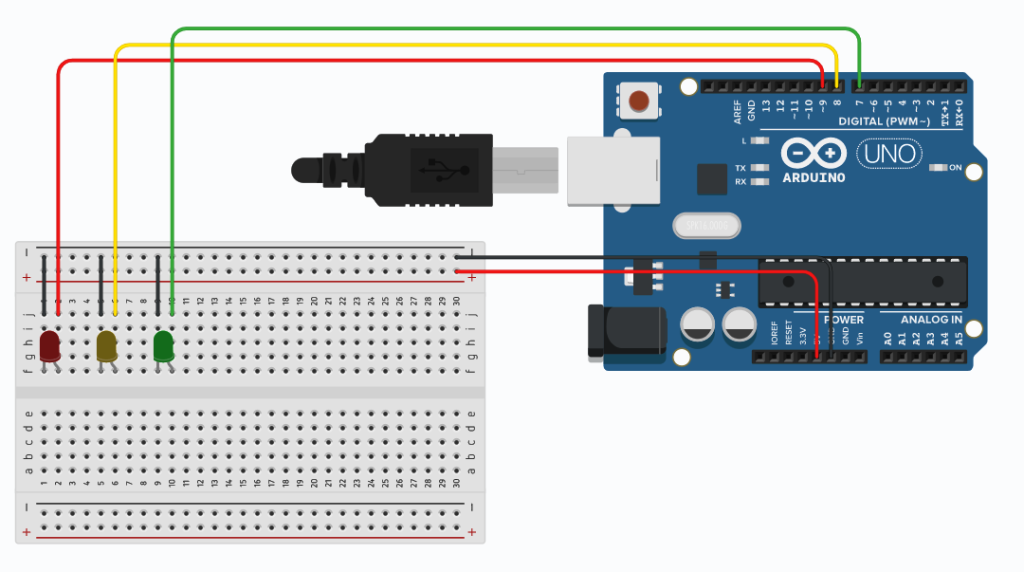
Circuit Diagram
Hookup Hook the GND pin (Negative Pin) of all led to Pin GND of Arduino. Connect Red LED VCC Pin (Positive Pin) to Pin 9 of Arduino. Connect Yellow LED VCC Pin (Positive Pin) to Pin 8 of Arduino. Connect Green LED VCC Pin (Positive Pin) to Pin 7 of Arduino.
EMMANUEL ADU DONKOR
Am Emmanuel ADU Donkor CEO of LEARN STEM AFRICA